High Voltage Ceramic Capacitors for Electric Vehicles


Electric vehicles (EVs) have accelerated the demand for high-performance, high-reliability capacitor technologies.
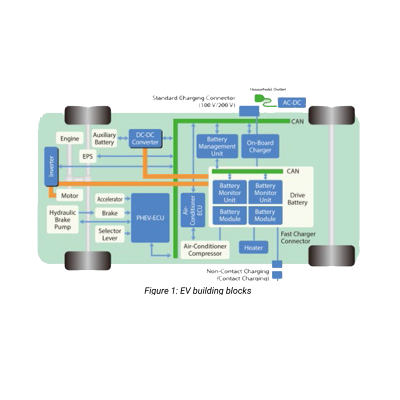
The wide array of voltage, power, and size requirements of the various electrical subsystems in modern EVs necessitates careful capacitor selection by designers. As shown in the blue segments of figure 1, these subsystems include AC-DC conversion, DC-DC conversion, power management, and battery monitoring, to name a few.
Which Type of Capacitor is Best for Automotive?
The four most common capacitor topologies that meet the strict quality and reliability demands of automotive AECQ-200 standards are aluminium electrolytic, tantalum, polymer film, and ceramic.
- Aluminium electrolytics have wide voltage and capacitance ratings at attractive price points but suffer from reliability issues due to electrolyte volatilization and leakage.
- Tantalum devices have excellent electrical stability over a wide temperature range but suffer from lower voltage ratings and potential short circuit failure modes.
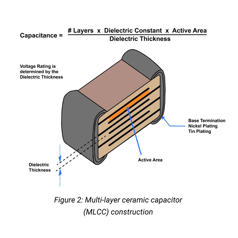
- Polymer film capacitors are widely used in industrial circuits due to their excellent inrush current handling capability and high reliability but may be unsuitable in many automotive applications due to their large form-factor and high relative price. A multi-layer ceramic capacitor (MLCC) is shown in figure 2.
- Ceramic capacitors - MLCCs consist of multiple layers of electrodes separated by ceramic dielectrics. The dielectric thickness determines the voltage rating, and the size and number of electrode layers determine the capacitance. The ends of the ceramic stack up are plated to form the electrodes for connection to the outside world.
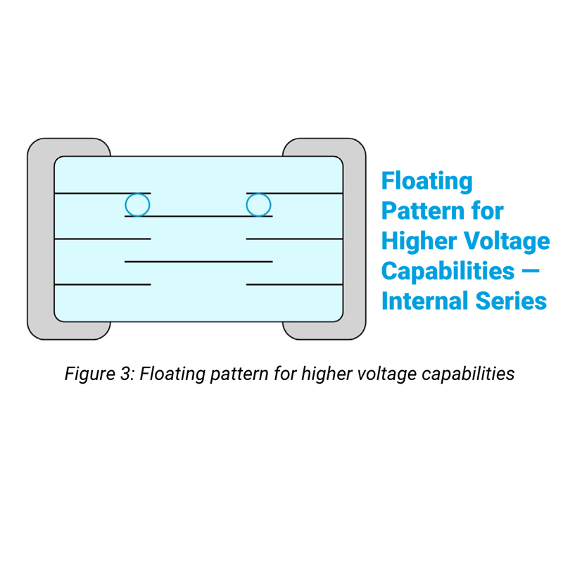
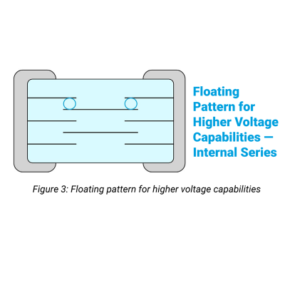
In high voltage applications, the voltage rating can be increased through the use of a slightly different structure employing floating electrodes. As shown in figure 3, these floating electrodes create two series capacitive layers, effectively splitting the voltage potential.
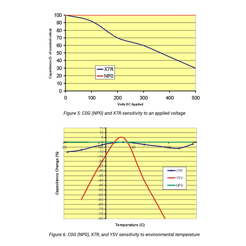
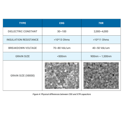
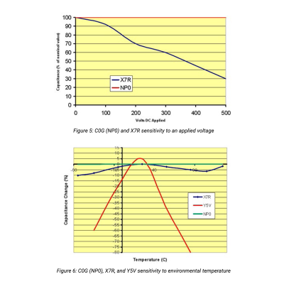
When considering MLCCs for high voltage applications, designers should also know that ceramic dielectrics are not all created equal. Capacitors are typically assigned a three-letter code based on their operating temperature range and environmental sensitivity for a given dielectric. Two standard codes are C0G and X7R. Figure 4 highlights the differences between these two capacitor codes.
Figures 5 and 6 demonstrate how these capacitor codes behave with different DC voltages and temperatures. As one can see, C0G (also called NP0) is extremely stable across voltage and temperature. This stability does, however, come with a tradeoff of cost and physical size.
The ceramic capacitor stands out for its wide voltage range and low series resistance (ESR). These characteristics make it particularly well suited to many automotive applications. However, understanding the structure and composition of MLCC capacitors is critical to selecting the proper variant and designing a successful product.
X & Y Capacitors
In many high voltage AC circuits, capacitors are required on the power input lines for electromagnetic interference filtering. MLCC capacitors can be well suited for this task and are generally divided into two rating classes: X and Y.
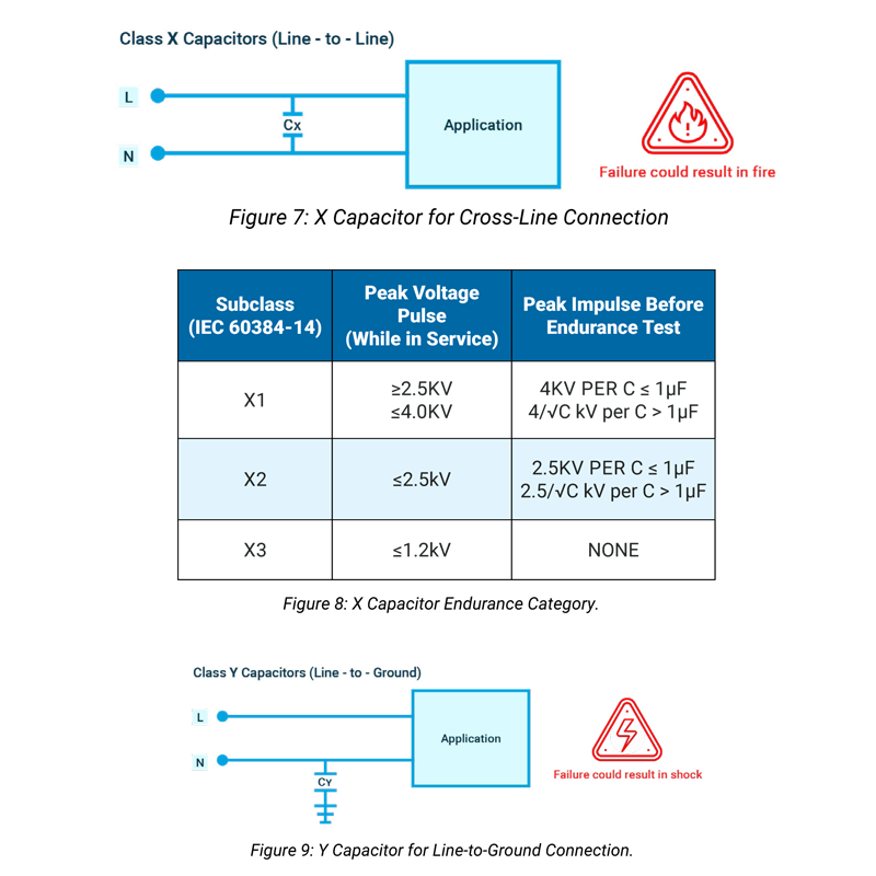
As shown in figure 7, X capacitors are used for line-to-line cross-connections. They are designed to fail in the short circuit mode to activate upstream overcurrent protection devices like fuses or breakers.
X capacitors are subcategorized by their voltage pulse endurance, and must be adequately chosen for a given application to guarantee safety. Figure 8 presents the ranges for X1, X2, and X3 capacitors.
On the other hand, Y capacitors are used in line-to-ground connections, as shown in figure 9. These capacitors are designed to fail in the open configuration, with a safety goal of preventing high voltages from reaching user-accessible parts.
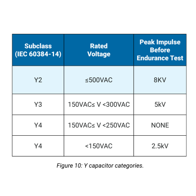
Y capacitors are subcategorized by their pulse endurance and their overall voltage tolerance. Figure 10 presents the ranges for Y1 to Y4 capacitors.
In automotive applications, these capacitors are used to protect battery cells, high voltage buses, data lines, and other electric drive system components from harmful EMI noise.
High Voltage Subsystem Examples
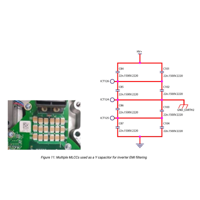
The following examples present use cases for MLCC capacitors in high voltage electric vehicle subsystems. A practical application example comes from the compressor motor of an EV air conditioning system. This motor is powered by an AC inverter and requires a 22nF, 1.5kV capacitor with a Y rating for filtering EMI to ground. The schematic and PCBA are shown in figure 11, where high voltage MLCCs were successfully implemented in production for this purpose.
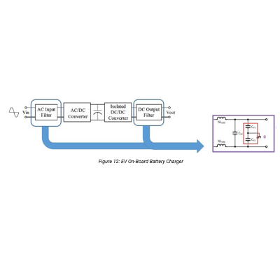
Another example examines the on-board charger present in EVs for recharging internal batteries. The top-level block diagram is shown in figure 12. In this example, the charger accepts AC shore power, and using a PFC AC-DC converter, generates the appropriate charging voltage for the batteries. The AC input lines and the DC output filter require X and Y high voltage capacitors for filtering. MLCCs were successfully employed in many of these designs to achieve a voltage tolerance greater than 630V while satisfying AECQ-200 requirements and meeting physical size targets
Conclusion
Electric vehicle systems have created new demands for high voltage, high-reliability capacitors, particularly in X and Y filtering circuits.
MLCCs are available in a wide range of structures and compositions and can be well suited to satisfy these demands.
MLCCs can be used to provide high voltage ratings, low ESR, and favourable cost and size trade-offs from AC-DC converters to high power snubbers.