The Application of Capacitors in Power Supply Regulator Circuits


Advanced Consumer Electronic Devices
Advancements in electronic technology over the last decade have led to smarter consumer electronics.
As devices become smarter, the components used to power them are shrinking, resulting in small, but incredibly powerful devices — ones small enough to fit inside a pocket or around a wrist.
With these smaller, denser designs, it can be impossible to separate analogue and digital domains in the layout, as best practices used to dictate years ago.
Today, design engineers are compelled to use many capacitors in the power network to attenuate high-frequency digital noise. Circuits are designed to expect pure, clean power without noise that will impact analogue circuits.
Capacitors in Power Supply Regulator Circuits
In a voltage regulator, capacitors are placed at the input and output terminals, between those pins and ground (GND).
These capacitors’ primary functions are to filter out AC noise, suppress rapid voltage changes, and improve feedback loop characteristics.
They are also used as bulk energy storage, providing instantaneous current to either the input or the load, as needed by design. Capacitors are critical components to all voltage regulator circuits.
Fundamental Parameters of Capacitors
The dielectric material, and the physical design structure, used to manufacture different types of capacitors, give them different characteristics. Before describing the characteristics of capacitors, we should first review some of their key parameters.
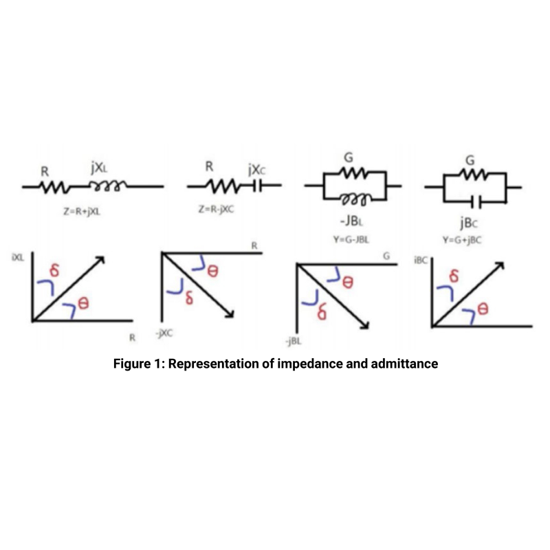
- Resistance: The symbol R refers to the capacitor’s DC resistance, described by the ratio of DC voltage to current through the conductor.
- Reactance: The symbol X is the impedance part caused by inductance and capacitance in the AC circuit, including inductive reactance (XL) and capacitive reactance (XC).
- Impedance: The symbol Z is a composite parameter. The real part is resistance, and the imaginary part is reactance. Total impedance can be expressed as: Z = R + jX.
- Conductance: The symbol G refers to the ratio of the direct current to the voltage through the conductor. Conductance is the reciprocal of the resistance.
- Susceptance: Symbol B is the imaginary part of admittance, including capacitive (BC) and inductive (BL) components.
- Admittance: The symbol Y is the reciprocal of the impedance Z, and therefore also a composite parameter. The real part is the conductance, while the imaginary part is the susceptance. Admittance can also be expressed as: Y = G + jB
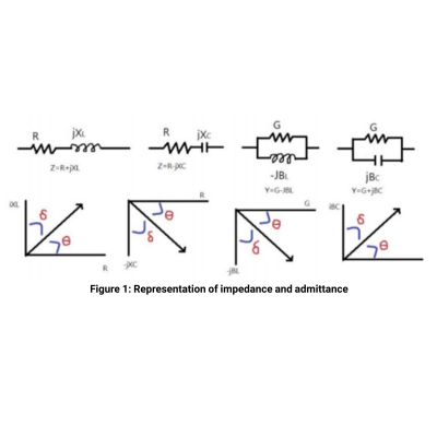
Figure 1 in the image gallery shows that when elements are connected in series, a positive θ indicates a more inductive component, while a negative θ indicates a more capacitive component. At exactly θ = +90°, the impedance would be entirely imaginary, and it would indicate a pure inductive element.
At exactly θ = -90°, the impedance would again be entirely imaginary, indicating a pure capacitive element. If the elements were connected in parallel, these relationships would invert; θ = +90° would indicate a capacitive element, while θ = -90° would indicate an inductive element.
General Characteristics of Common Capacitor Types
The characteristics of several types of common capacitors are presented in the table below:
|
Type |
Advantages |
Disadvantages |
| Film |
|
|
| Ceramic |
|
|
| Tantalum |
|
|
| Aluminium |
|
|
Advanced Consumer Electronic Devices
There are no real, physical components that are purely resistive, capacitive, or inductive. All real passive components can be characterized as a combination of these ideal components, however.
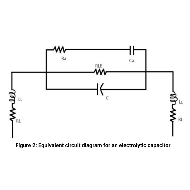
When a real-world resistor, capacitor, or inductor is represented as a combination of all three of these elements, that is called an equivalent circuit. An equivalent circuit diagram for an electrolytic capacitor is shown in figure 2 within the image gallery.
In Figure 2, Ra and Ca are the resistance and capacitance caused by dielectric absorption. RLE is the resistance due to leakage current. RL and LL are the resistance and inductance introduced by the pin leads of the package.
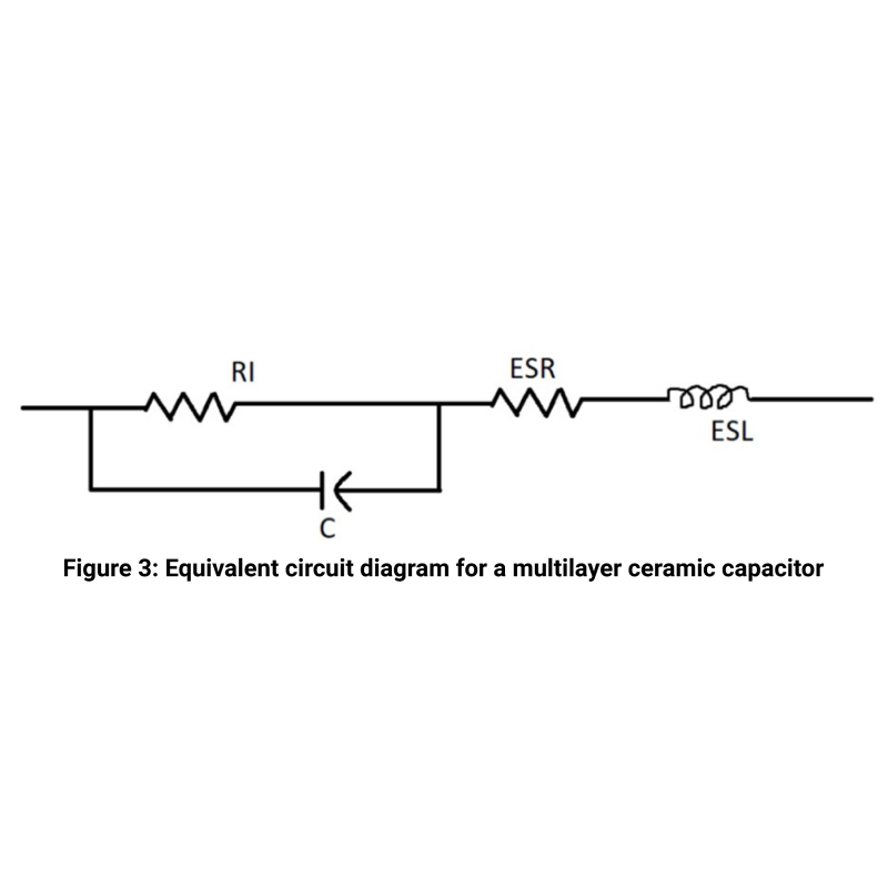
In a multilayer ceramic capacitor, the equivalent circuit is slightly different because of its physical construction. There is a series resistance (ESR) and a series inductance( ESL) and a leakage resistance. This is shown in figure 3.
Measured Capacitance Characteristics
Given these general characteristics of capacitors, any specific capacitor device can be characterized by measuring a few key parameters.
By measuring series resistance (RS), capacitance (CS), and inductance (LS), plus the magnitude (Z) and angle (θ) of the impedance vector, we can fully characterize a real capacitor.
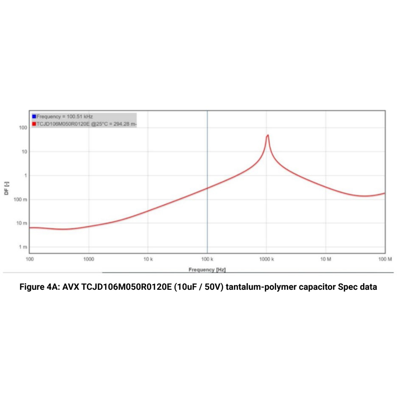
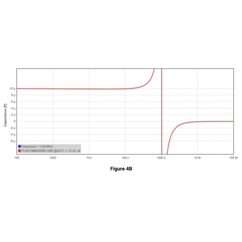
Let’s look at the AVX TCJ, a tantalum-polymer capacitor (TCJD106M050R0120E), as an example. The data within figure 4A and figure 4B was gathered from a SPiCAT simulation.
Figure 4 shows that the 50V / 10uF Tanpolymer capacitor loses its capacitance when f> 1MHz, showing weak sensitivity.
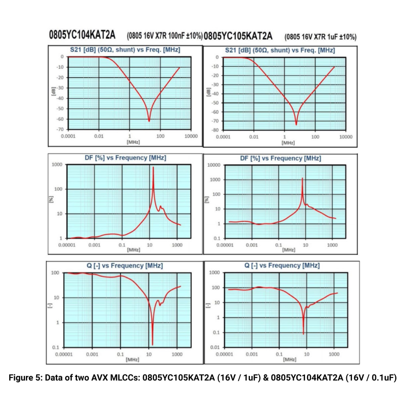
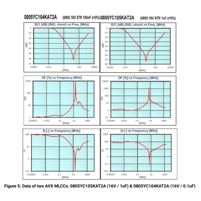
The tables in figure 5 within the image gallery show the spec data of another two AVX MLCCs: 0805YC105KAT2A (16V / 1uF) & 0805YC104KAT2A (16V / 0.1uF).
These two capacitors maintain a high Q value within a frequency of 1MHz, showing good capacitive characteristics
Selecting the Right Capacitor
In order to achieve better noise attenuation when using multiple capacitors in parallel, capacitors with different capacitance (C) and equivalent series resistance (ESR) should be selected.
This will cause the attenuation curve to start from the first pole and end at the last zero point. The capacitor with the largest capacitance determines the start frequency of attenuation, and the capacitor with the smallest capacitance determines the end frequency of attenuation. Reducing the pin length to minimize equivalent series inductance (ESL) is also crucial.