Capacitor for Audio Applications


Top of the range audio equipment has developed into a small, but pricey, specialist field of home audio electronics.
Qualified manufacturers are constantly endeavouring to meet the ever-growing demands of audio enthusiasts for sound enjoyment and prestige value.
Passive components, such as capacitors for example, may not be at the centre of public interest when compared to active components, however, they form an indispensable part of the overall result.
Why WIMA?
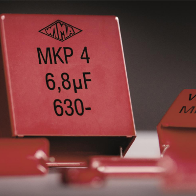
Firstly, WIMA components provide a welcome visual improvement to a PCB due to the precise geometry of the casing combined with the attractive red colour and imprint. Especially with equipment which has tube amplifiers and/or where it is possible to see the inner workings through a perspex lid, WIMA components, both the smaller and the larger types have an undeniable aesthetic charm.
However, WIMA understand that appearance is not enough. The inner workings of these capacitors, i.e. their performance also has to satisfy the high demands of the leading manufacturers and fulfil their specific and demanding requirements. Just to produce quality, which all component manufacturers claim to do, is not enough in this case. WIMA have, therefore, succeeded in keeping well ahead of the others as regards the performance of their capacitors.
WIMA’s success lies in the fact that, due to the choice of material, the principle of construction and their first-class processing know-how, their capacitors come closest to the goal for the ideal capacitor.
Applications
In the audio transmission chain equipment starting with the CD player, record player and tuner, through to the transducer, pre-amplifier, power amplifier and finally in the crossover of the loudspeaker, capacitors with an almost endless variety of different capacitance and voltages are used.
The majority of the applications are directly in the signal path and can have a direct influence on the audio signal. Great care should, consequently, be taken in the choice of suitable capacitors.
Audio applications can be grouped into three basic fields:
- Applications in the signal path
- Functional tasks
- Use in voltage and support
By using optimal capacitors versions in all three fields of application, distinct improvements in the tone can be achieved, or, to be correct, the sound will be less affected.
The capacitors in the signal path certainly have the most direct influence on the audio signal. Consequently, real improvements in the sound can be achieved just by exchanging inferior quality capacitors with high quality capacitors.
Another very important criterion is the functional capacitors, which can be the cause of signal distortions in applications such as CD players, D/A-A/D transducers and pre-amplifiers.
Capacitors for voltage support have less influence on the precise re-production of the music, providing they have sufficiently large capacitance. However, they should not be disregarded in genuine high-end equipment. With qualified optimisation in this field too, ultimate refinements in the conception of the equipment can be achieved.
Film capacitors – the optimum solution
Basically, film capacitors offer the optimum solution to problems in all areas of application. Only the position of the energy storage/smoothing capacitor is to be covered by electrolytic capacitors due to the limited capacitance with 'C max to 680 μF' for film capacitors. In all other positions, plastic film capacitors are far superior to other technologies both in performance and reliability.
Plastic film capacitors are offered by WIMA in many different versions. The dielectric used constitutes the main distinguished criterion:
- Polyester (Mylar) MKS/FKS versions*
- Polypropylene MKP/FKP versions*
- Polyphenylene-Sulphide SMD-PPS*
*WIMA-types
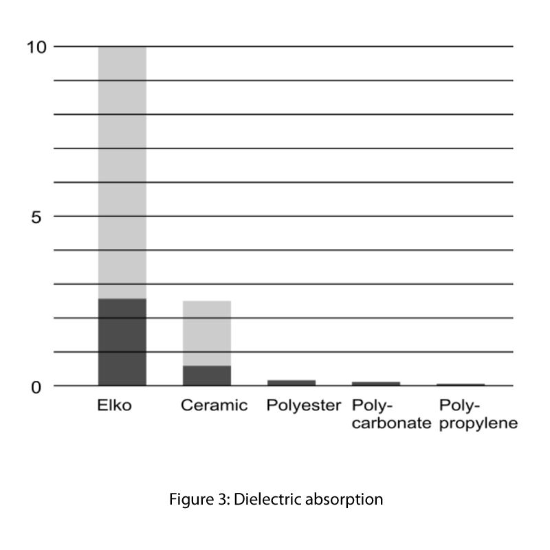
Dissipation factor
In AC voltage operations, a continuous change of polarity of the capacitor electrodes and consequently of the dielectric takes place. The resulting friction in the molecular structure is converted into heat. The losses incurred in this polarity change are dependent on frequency and also on the applied voltage. Furthers losses are the so-called heat losses. They stem from the resistive component of the 'current carrying parts' of the capacitors; leads, schoopage and capacitor electrodes.
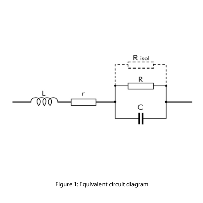
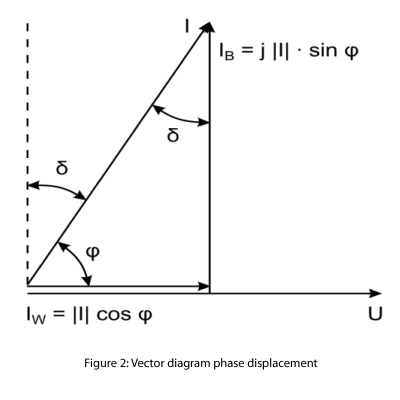
From the equivalent circuit diagram of the technical capacitor (see Figure 1) results the calculation of the dissipation factor in accordance with the vector diagram (see Figure 2)
Consequently capacitors with the lowest dissipation factors show the least signal distortions. Especially if polypropylene capacitors are used, the remaining dissipation factor is so small that noticeable displacements no longer occur.
Polypropylene – the ultimate solution
For applications in the audio field, polypropylene versions are, in principle, the most suitable as they have the lowest dissipation factor. Polypropylene capacitors are therefore available in both metallized and film/foil technology. The capacitance ranges from
C = 100 pF to C = 10 μF
Thus, almost all fields of applications can be completely covered by polypropylene capacitors. In some cases applications, for example, in loudspeaker crossover networks, higher capacitance values are required. In these cases, as an exception, it is possible to use polyester capacitors which are manufactured as special versions with a capacitance value up to
C = 680 μF
The dissipation factor of polyester is considerable higher than that of polypropylene but it is 20 times lower than comparable audio frequency electrolytic capacitors.
Structural Characteristics
To achieve a faithful musical reproduction, every designer has the intention of using electrically ideal components in the development of high end equipment. However, ideal components only exist in theoretical physics. With every technical / real component, as in the case of the capacitors, further possible disruptive influences occur. The actual behaviour of a real capacitor can be derived from the equipment circuit diagram of the capacitor. The equivalent circuit diagram shown at
the top of figure 1 demonstrates parasitic component characteristics such as:
- L = Self Inductance
- r = Ohmic Resistance
- R = Polarisation Losses in the Dielectric
- Risol = Insulation Resistance / Residual Current
By means of suitable structural measures minimising the parasitic components, WIMA has come very close to creating an ideal capacitor.
The polarisation losses referred to as R can, as has already been discussed, be reduced to a minimum by using polypropylene.
As a result of the very good insulation properties of almost all plastic film in the region of specific volume resistance > 1018 Ω x cm the insulation resistance parameter may be disregarded. This parameter is more critical in the field of electrolytic capacitors which work specifically with residual current. Here, the values are 100-1000 times higher than in plastic film capacitors.
The structural features we are mainly concerned with are, therefore, self-inductance (L) and ohmic resistance (r).
Self-inductance
In the field of audio application, very precise pulse reproduction is required. This is assessed in the pulse behaviour criteria. In particular, When seeing audio signal dynamic jumps of up to 100 dB occur. This means a voltage of
100 dB → U1 = 1 : 100000
Both the parasitic self-inductance and the ohmic resistance of the capacitor have a de-emphasising effect on such voltage changes. Furthermore, such voltage curves are made up of a high proportion of harmonics of fundamental oscillation. Therefore, the frequency spectrum transmitted exceeds the audible range of f = 20 Hz to 20 kHz considerably. In this case, the transmitting frequency is up to f = 100 kHz.
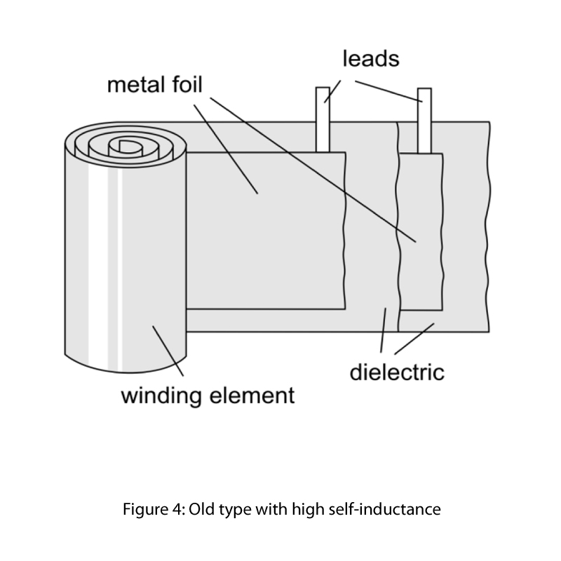
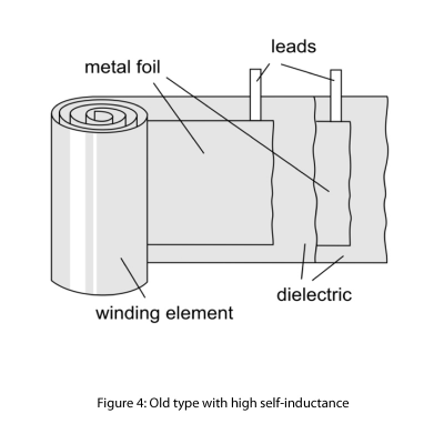
Modern WIMA high-performance capacitors are produced as radial components with end surface contacts. When compared to conventionally manufactured axial wire
contact versions, parasitic self-inductance is reduced to a minimum. See Figure 4
The tape length of the winding element determines the value of the selfinductance.
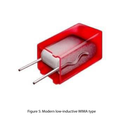
WIMA plastic film capacitors are, now, contacted over the surface of the whole tape length. The self inductance of the winding element is, therefore, short-circuited. See Figure 5.
The remaining self-inductance is reduced to the smallest resulting conductor loop possible, which is made up of the
- width of the winding element
- remaining length of the leads
Values for practical purposes: L= 1 nH/mm
- Example:
- lead length 2 x 3 mm
- PCM 5 mm
- Lself ≈ 11 nH
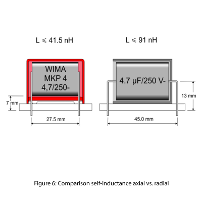
Modern radial capacitor technology complies with the efforts being made in audio applications to keep the signal paths as short as possible.
The old axial designs, often still offered as special audio capacitors, have the striking disadvantage of unnecessarily lengthening the conduction paths on the PCBs and, because of the larger structure and longer remaining length of the leads, they have considerably higher self-inductance.
Figure 6 shows the different self-inductance of axial / radial construction.
The pulse behaviour of axial constructions is, therefore, much worse than that of modern radial ones.
The old axial versions may just offer slight advantages in the installation of crossover networks in outdoor wiring. For such applications, however, radial WIMA components
are also available with long leads.
Further advantage: Low ohmic resistance
The large surface contact, over the whole length of the winding element, represents a further advantage of modern WIMA capacitor technology. With contact over a schoopage layer, the largest possible area of the winding element is contacted and this inevitable results in the lowest ESR.
The structure form of the capacitors electrode also influences the dissipation factor/phase angle and pulse accuracy. In general, there are three different constructions available for use in audio applications.
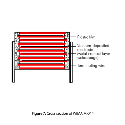
Single-sided metallized versions
One of the most common capacitor versions is the single sided metallized structure shown in Figure 7. Such a capacitor consists of two layers of film metallized on one side with aluminium. Contacts to the leads are made through a schoopage layer.
This construction has the advantage of being the best C/V product i.e. the smallest possible box size at a given capacity. Therefore, high capacitance values can be produced, as required in crossover networks. For example, the decoupling of the final power amplifier.
However, these types are disadvantaged in that the capacitor current is only conducted by the thin aluminium metallization. When compared to the double-sided metallized and film/foil version described in the following section, the above construction has the least favourable pulse behaviour. In ultra high-end equipment, such capacitors should therefore only be used when the required capacitance values are not available in the higher rated versions.
Double-sided metallized versions
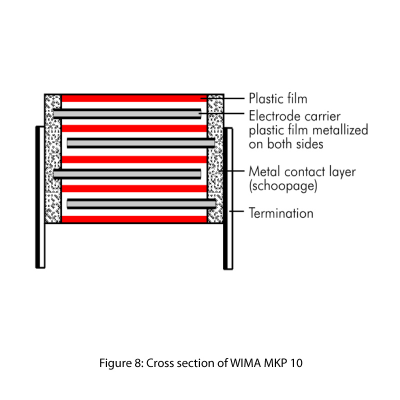
To cover positions with high capacitance values in audio applications, the principle of the double-sided metallized construction used in the WIMA MKP 10 series and
shown in Figure 8, is the most suitable.
Here, the capacitor electrode is made of film metallized on both sides. The capacitor is produced with 4 layers of film. Such a construction has a 5-10 times greater
pulse rise time and a much better pulse behaviour due to the double contact of the metallization and also benefits from the improved toothed attachment of the schoopage due to the enlarged spaces in the winding element. See Figure 8
The good contact to the capacitor electrode also has a favourable effect on the dissipation factor. Types which are metallized on both sides have a 30-50% lower dissipation factor than comparable versions metallized on one side only.
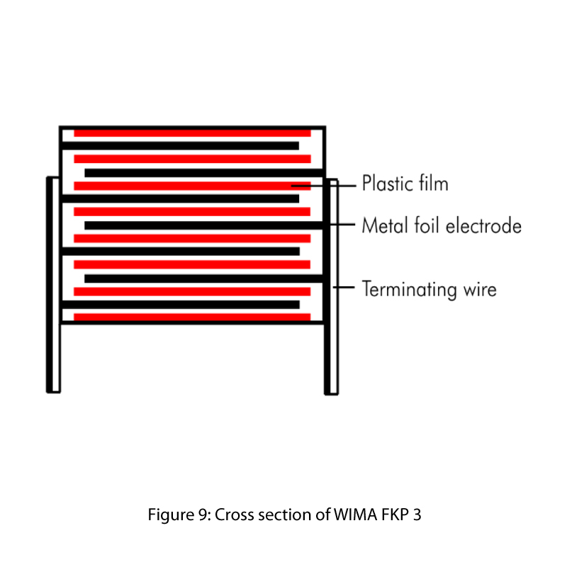
Film/foil versions
With regards to audio applications, WIMA film/foil capacitors with polypropylene dielectric represent the non plus-ultra. In Figure 9 the capacitor electrode is shown as a massive metal foil.
As a result of the good contact of the capacitor electrodes at the end surfaces to the Leads –“direct bonding”, as well as the large cross-section of the electrode foil, such versions have outstanding pulse behaviour. For example:
- WIMA FKP 02 (PCM 2.5 mm)
- WIMA FKP 2 (PCM 5 mm)
- WIMA FKP 3 (PCM 7.5 + 10 + 15 mm)
Film/foil constructions cause practically no attenuation of the audio signal and, therefore, provide absolutely pulse accurate reproduction.
Furthermore, WIMA FKP 2 versions are available as a precision capacitor with a tolerance of up to:
C/C = ± 2.5% (1% on request)
However because of the rapidly increasing box sizes, this film/foil technology can only be used in the capacitance range of:
C = 33 pF ... C = 0.033 μF
Higher capacitance values are best covered by the types that are metallized on both sides in accordance with the preceding explanations.
Applications in the signal path
Efficient WIMA polypropylene capacitors are available for all the fields of audio applications mentioned before.
The field of applications in the signal path covers the greatest capacitance range. Coupling capacitors of C = 100 pF are used, for example, in transducers and pre-amplifiers, as well as values above C = 10 μF in crossover networks.
Based on the respective demands of the equipment manufacturers, from the point of view of what is technically possible, the following recommendation may be given
for application:
- WIMA FKP 02 C = 100 pF to C = 0.01 μF
- WIMA FKP 2 C = 33 pF to C = 0.033μF
- WIMA FKP 3 C = 100 pF to C = 0.22 μF
- WIMA MKP 4 C = 0.01 μF to C = 10 μF
- WIMA MKP 10 C = 1000 pF to C = 47 μF
Functional tasks
Functional capacitors are generally used in the field of small signal processing. Typical for this are applications in pre-amplifiers, D/A-A/D transducers, filters, in tuners, CD-players, record players etc. The capacitance values required here are in the lover capacitance range. Highly precise 1% versions are often demanded for filter, timer and integration applications or as sample and hold capacitors in transducers.
For this purpose it is always suitable to use the WIMA FKP 2 series which is also available on request with a nominal tolerance of ΔC/C = ±1%. Furthermore film/foil capacitors show the best time constant. They therefore remain within the specified parameter even after many years of use.
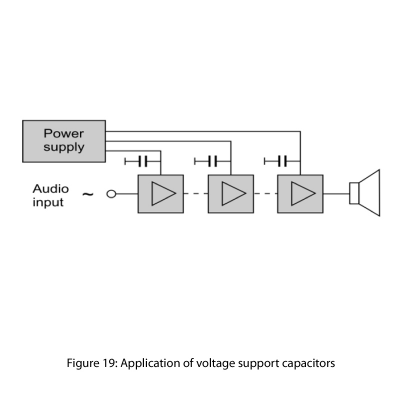
Use in voltage support
Reservoir capacitors have the task of storing energy and passing it on as quickly as possible when needed. They are directly connected to the voltage supply of the respective amplifier stage. See Figure 19
When high dynamic jumps occur in the audio reproduction, high power demands are suddenly made on the amplifiers which cannot be provided directly from the
central power supply with the electrolytic energy storage capacitor.
Such a power bounce would lead to a drop of the supply voltage and, inevitably, distorsions and unfavourable pulse behaviour.
To avoid this effect, capacitors in the capacitance range of: C = 0.1 μF ... 10 μF are connected against the ground directly at the feeding point of the voltage supply of the respective amplifier stage. When power bounces occur, these capacitors provide the required energy as quickly as possible and effectively avoid voltage drops.
In the subsequent pulse pause, the reservoir capacitors are recharged.
Since these capacitors are not used in the signal path, polyester versions are adequate e.g.
- WIMA MKS 02 PCM 2.5 mm Cmax = 1μF
- WIMA MKS 2 PCM 5 mm Cmax = 10μF
- WIMA MKS 4 ≥PCM 7.5 mm Cmax = 680μF
Furthermore, WIMA MKS capacitors have the advantage of very small box sizes, i.e. the designer is in a position to use the largest possible capacitance value within given space requirements.
Conclusion
WIMA plastic film capacitors offer the best possible properties for all fields of audio application.
Special constructional features which are made-to-measure to suit each particular field of application, combined with an ultra modern, automated manufacturing process and a special quality assurance system WPCS (WIMA Process Control System) in accordance with ISO 9001/2000, form the basis of WIMA’s position in the High End audio sector and their clear distinction from other manufacturers.